![]()
Flowbench Design Guide
|
|
|
|
DIY Flowbench Design and Construction What’s a flowbench: A flowbench or ‘air flow bench’ is a tool to measure the air flow capabilities of anything that’s required to do this. It is (and has been for decades) an invaluable tool to any one interested in increasing the performance of combustion engines. Inlet manifolds, ports, valve profiles, exhaust systems, intercoolers, throttle bodies, air cleaners, 2 stroke porting etc etc. the list of items that can be tested is endless. Engine modifiers and designers (and even those dealing with fluid dynamics and aeronautics) will find this an excellent project! The actual airflow figures are generally the goal but the ability to flow air under controlled conditions also allows the user to study air flow characteristics like velocity, turbulence, swirl, tumble, distribution etc. and anyone who’s really done the ‘hard yards’ of engine development will tell you this is the secret. It’s the ‘quality’ of air flow, not necessarily just ‘quantity’ that counts.
Purpose of this technical article: To allow the design and construction of a fully functional, compact, inexpensive and accurate flowbench. There are many ways to build a flowbench, this direction was taken after much research and experimentation. It meets all the design goals and requires minimal time and effort to construct. Construction details are kept general and to be used as a guide only. Dimensions etc. are not critical and should be adjusted to suit the materials available and your construction techniques. All wiring must be carried out by qualified tradesman and be in line with your local regulations. We provide this information in good faith and are not responsibly for any direct or consequential damage or claims. There are many excellent books, papers and web forums available to discuss the approaches to doing the actual modifications and testing so I will not, at this stage, be going into anything more than the basic test procedures and some simple concepts. Please see the links page for some research reading, also keep an eye out for future products and tech articles with additional measurement tools and information. Why aren’t flow bench’s more common: Commercial flow benches are expensive and usually found only in the ‘higher end’ specialised workshops. DIY constructers are usually left confused by the many different design ‘ideas’ floating around and the simple concept can be easily lost in complex fluid dymanic’s formulas (not needed for building or using!). There is also absolutely no need to drag computers, electronic sensing and control into the standard DIY approach. We’ll keep it simple, that’s how we all like it, at least to get started! Principle: A flowbench needs a source of airflow, a system to measure the actual air flow, a method to control the test pressure of air being applied and an area to mount the device under test. The test piece is mounted and a certain pressure, called test pressure (eg 28” of water) is applied to it and the resulting air flow measured. The chosen way to measure the air flow is by measuring the pressure drop across an ‘orifice’ with a known characteristic. Greater air flow will cause a greater pressure drop. Simple ‘water column’ manometers are used to measure the test pressure and the flow rate, no need for complex tables or spreadsheets. This method is not only easy but it’s very accurate, it is independent of all the atmospheric variables (air temp and pressure) that plague other methods. Any variations are applied to the test piece as well as the measuring system (it’s called ‘ratiometric’ measuring). It is the method also used by the industry standard flowbench’s from the Superflow company. To cover a full range of testing accurately we need several orifices as each has a limited range of flows it can be used for.
Briefly for now- when testing you adjust the airflow from the airbox to set your test pressure and then read the inclined manometer, this shows the pressure drop across the orifice as a percentage. So if the orifice you are using to measure with flows 145CFM and the reading is 84% then your test item is flowing 0.84 x 145 = 121.8 CFM.
When first researching flowbench design its hard to understand that it doesn’t matter what test pressure you choose, the principle of reading the percentage of flow off the inclined manometer is the same. Even though your inclined manometer has a certain ‘rise’ and the orifice’s were tested at a certain pressure, the bench is performing a ratiometric comparison that ensures that this is basically irrelevant! Components: Airbox-
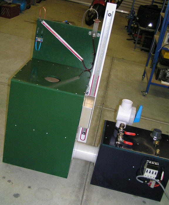
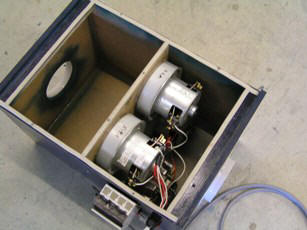
By keeping the airbox a separate unit it allows compact storage and easy modifications or upgrading if needed later. A simple PVC plumbing pipe slides into either end to attach to the main flowbench cabinet and the whole unit can be turned around to blow instead of suck. Air ‘bleeds’ are incorporated and can be relocated so they are upstream, regardless of direction, to allow the fans to draw a constant air flow without restriction which important for their internal cooling. The volume is not important (it’s not a plenum box). It just needs to be large enough for a number of motors and have smooth passage of air in and out. Vacuum cleaner motors are used as an air source. After testing many different industrial blower units and other options these were found to be very efficient and capable of pulling large pressure and flow numbers (many blowers etc flow large volumes but as soon as you restrict this they cannot provide sufficient test pressure or visa-versa). Second hand vacuum cleaners are very easy to find and often disposed of with motors still functioning (five out of six I obtained were fine), the price of new motors was prohibitive with many machines worth less than their replacement motor. Try to source motors from hi wattage cleaners, though this can be misleading as motor wattage and efficiency are two different issues, stick to well known brands if there’s a choice. Multiple vacuum motors are used for increased flow capability, if the test pressure you use is reduced then you can get away with less motors, but I feel your better of with extra capability built in ready for testing large flowing items. My development unit has 4 motors and I rarely use them all, but then I’m usually working on motorbike heads and not drag cars!
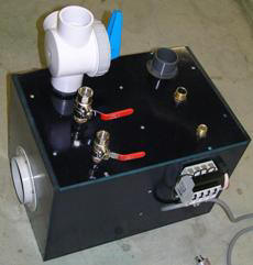
Switches on the box for each motor can allow the number required to be turned on only as needed, reducing noise, electrical load and wear and tear. ‘Staggered’ turn on reduces peak current draw and prevents circuit overload of your workshop fuse panel. Don’t underestimate the current draw of these motors, it takes a lot of power to move large volumes of air at reasonable pressures (power required increases by the cube of test pressure!). I recommend you test the current draw of each motor and record it to ensure your power supply is adequate. Into the box lid are seen the adapters that mount the air valves (air ‘bleeds’), these are used to adjust the air flow so that the desired test pressure is applied to the test item. I found by using three different sized valves that I had course (quick) control and then fine adjustment also. Any type of valve or taps could be used, my large valve is one often used on spas and pools and the smaller two are standard ball valves. All are found at hardware/plumbing stores. The valves should have adapters mounted on both ends of the airbox so they can be quickly re-located if the unit is reversed for blowing. Made from MDF wood the main box is glued and screwed together. The lid is removable for maintenance and construction and screws on, it’s sealed with foam ‘weather strip’ attached to the box lip. The motors are attached by bonding with silicon adhesive to the divider board (this was a temporary method that has now remained without issue). Wiring runs out via an electrical conduit ‘gland’ but could easily be silicon sealed instead. The air inlet/outlet adapters on each end are PVC ‘flare’s’ from a plumbing hardware store and are glued and screwed around a hole cut into each end of the box. The inside edge of the fan holes and the main box holes are chamfered for maximum air flow (I used a router, but could be filed by hand easily). Vertical manometer-
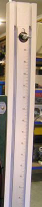
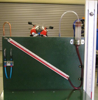
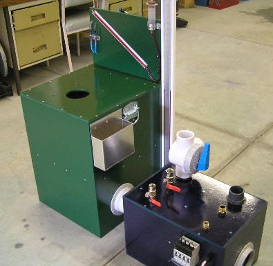
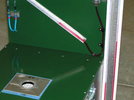
The vertical U-tube manometer on the side (large white strip in the photos) is for confirming the test pressure that’s set by adjusting the air bleeds on the airbox. A strip of wood is used as a base and has a small groove routed into it to locate the clear plastic hose (or you could just clip/glue it on the surface). One end of the hose is open to atmosphere and the other is taken down into the cabinet plenum below the test piece. The scale used is an aluminium ruler, wipe off the numbers (with fine emery paper) and re-apply with rub on transfers from office/craft store. The scale has zero marked half way along with numbers progressing above and below, this allows measurement of either pressure or vacuum (sucking or blowing). Each inch marking is now to be re-labelled as two inches (i.e. 1 inch of water rise in one ‘leg’ now reads 2 inch’s on scale), this is due to the actual pressure being the difference between the two sides. This difference in water levels is a true reading regardless of tube diameter variations etc. It’s known as a primary standard. The ruler is mounted with slotted end holes and wing nuts, this allows simple sliding of the scale up or down so that the water level at rest is at the zero mark. Sure beats trying to add and remove water to calibrate due to evaporation over time! The length of the manometer only needs to allow for your maximum test pressure but I’d add extra so a sudden blockage of air flow through test piece won’t cause the water to overflow, the one in the pictures is 39” long. Water is used as the medium with a small amount of red food colouring added for visibility. Be cautious of using alternate fluids to water as density changes effect operation and calibration is in inches of water only. The vertical manometer unit in the photo can be removed for flowbench storage as it mounts to cabinet back with 2 captive bolts and wing nuts. Inclined manometer-
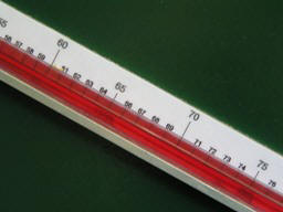
On the backboard can be seen the inclined manometer, it’s for measuring the actual airflow and is simply a more sensitive way of using a manometer, what is of interest is still the height the fluid moves up vertically. By inclining, the fluid will travel a further distance for any change in height making it much easier to read small changes eg. If it is mounted so there’s 2” vertical rise for every 8” horizontal then a 1” fluid rise will show as 4” movement on the scale. The length is not overly important but longer will allow easier reading of small changes. The height, or rise (and therefore slope) should coincide with a convenient testing pressure, 7’’ is often used (the one in photo is 14” long and has a 7” rise), this is not critical, but if you choose a rise that is near a common test pressure and calibrate at that pressure then accuracy will be marginally better during normal use. The size of your bench design ‘backboard’ will really dictate the best rise vs length approach. Don’t have it rise too much or the steep angle will make for poor resolution of readings, a 30 degree slope generally works well.
The pressure drop across an orifice is to the square of the flow. If flow doubles, pressure goes up 4 times, therefore the scale on the inclined manometer must follow this non-linear rule, the scale is logarithmic. 0% is at marked at the top with 100% at the bottom end and as you approach 100% the scale should be greatly expanded so that each % reading is a widely spaced graduation. To produce the scale you can use the downloadable spreadsheet or the sample image and stretch to your required length. Printing, laminating and bonding to a strip of aluminium ‘right angle’ works fine. The hose is also bonded along the aluminium and small mounting slots are filed in the aluminium pieces ends to allow screwing to the backboard and adjusting the slope when doing final calibration. The straightness and hose internal diameter consistency will affect the accuracy slightly if poor quality is used; the one purchased here is just from a hardware store and proved more than acceptable. A reasonable sized water reservoir (‘well’) is needed to ensure accuracy as the level drops (research inclined manometers to learn why) and by using one that can slide up and down it allows easy adjustment of the level so that at rest it reads 0% on the scale. A large syringe body works well, a rubber stopper inserted in the top holds and seals the tube and a firm ‘saddle clamp’ allows the well to slide if pushed.
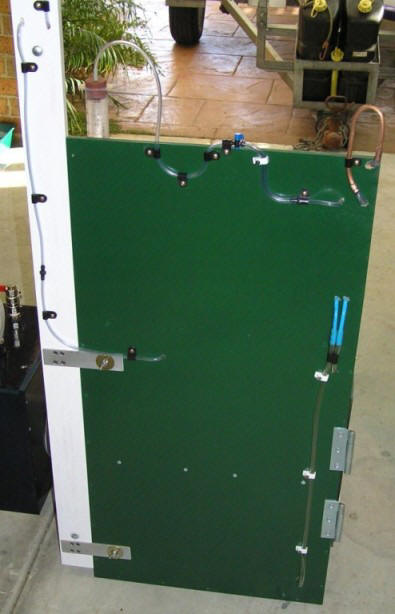
Each side of the inclined manometer goes to one side of the measuring orifice and by routing the tubes to fittings on the backboard the manometer ends can be swapped for testing by blowing instead of sucking. Pneumatic quick release fittings (blue pipes in photo) are used, but simple push in hose fittings would be fine. The top tube from the inclined manometer is run into the lower plenum chamber (via the fittings to allow swapping these lines) and the lower tube goes into the top plenum chamber. The tubes are run along the cabinet wall internally from one side to the other (fastened along back wall) and the ends are blocked, small holes are drilled along the length (1mm diameter about every 50mm) to give a better average reading of the pressure. A raised section (copper pipe in photo) was added so that poor testing procedures don’t cause all the fluid to siphon out of the tube if the manometer range is exceeded, pipe was added only as the hose was already cut too short to raise! Also, in the photo is a small inline tap at the top of the backboard that acts as a ‘needle valve’ and allows adjustment for dampening of the reading if it is pulsing; this is from a garden irrigation system. Orifice holes- The whole air flow measuring principle relies on the relationship of pressure drop across an orifice being directly related to the air flow through it. For this relationship to be true the orifice must be extremely thin (‘sharp’ edged) and the air flow must be laminar (straight, not turbulent) and there must be no interaction with surrounding objects like the cabinet walls. The design here has the orifice plate protected from the turbulent air that comes through the test piece by keeping it out of line, having a large surrounding protected area and using a laminar flow grid to straighten the air before measuring. The grid used is cut down from an industrial light fitting but they are also used widely as intake vents for household air-conditioners. During testing the grid was found to have minimal effect (the basic design is very sound) so only one was mounted above the orifices, ideally one should also be added below for when blowing, not just sucking. The orifice plate needs to have a number of holes so that a large airflow range can be accurately measured, this is required due to the non linear relationships of air flow to pressure drop across the orifice. Testing with an orifice size that allows a reading of 60%- 95% on the inclined manometer at your desired test pressure gives best results (good resolution on the scale). Orifice sizes should therefore cover a large range and allow for overlap. The design here allows any combination of orifice to be used, not just one at a time, this extends the capabilities greatly.
To change orifice range selection you just open the side door and remove/replace a bung covering the hole to block it from airflow. Each hole is numbered (to reference what it flows). The bungs are foam covered discs and under suction testing they just sit there and seal themself, for blowing they need their lower half fitted and wing nut used. Many designs I researched used some very impressive rotary orifice plate selection ideas that change the hole with the turn of a knob, feel free to design one but be very wary of sealing issues, choice of multiple orifice selection, hole precision and compromise of main bench design due to the size of the mechanism! A slide design (rather than rotary) could be easily incorporated on this bench. After experimenting unsuccessfully with machining and stamping of very thin gauge plates, the current orifice construction concept was reached. The holes are milled into a Perspex sheet and a steeply angled edge ensures that the edge is very sharp.
The edges must be angled steeply so that a sharp edge is formed and air does not ‘follow’ the tapper and become turbulent. The direction of air flow when measuring must be with the air flow hitting the flat side (taper down stream). The whole plate is simply inverted for blow testing. This design behaves as a true ‘sharp edge’, this was confirmed by testing on a Superflow SF-1020 bench at all reasonable pressures. Don’t bother trying to calculate your exact orifice flows using the many formulas published (unless you are prepared to compromise accuracy), in reality there is way too much error. I tried calculations at first to avoid accessing a commercial bench, tiny changes to edges or diameter etc effect flow characteristics greatly. Make the orifices as described and select approximate sizes for a good range (combinations of multiple orifices can later also be easily used to cross check bench accuracy). As a guide, the diameter orifice holes and tested flow rates (Superflow ST1020 bench) in the above plate are- Diameter mm Flow CFM at 15” water 51.85 209.5 42.38 139.5 29.98 70.4 21.16 35.5 9.92 7.8 Get your orifice’s flow tested on an existing bench such as a ‘superflow’ and record the figures, test orifices at the inclined manometers rise height (eg 7”) to aid in accurate calibrating. Flow rates at another higher pressure (eg 28”) can be taken also to check orifice characteristics at higher pressures if wanted. Flow rate data at a given pressure can easily be converted to any other using the chart that can be downloaded eg. if flow is given at 15” water it could be corrected to 7” etc if required. While making the orifice plate, get some sheet material and a make a calibration plate (it won’t hurt to make several of differing sizes also, though not required). Aluminium sheet is fine, accuracy is not that critical as it’s to be flow tested when completed. Make the hole just smaller than largest orifice hole (eg > 90 % flow, closer the better), if this is used to calibrate off the large orifice hole then all smaller ranges will fall into place automatically. Get this tested at the same time as the orifice plate and inscribe the flow data on it, including which side was ‘up’ during testing to allow for any edge imperfections. Getting the calibrating plate and orifice plate flowed should be fairly inexpensive as there is practically no set up time and only a couple of readings on each! A quick search of cylinder head porters/modifiers will reveal one in your area.
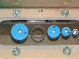
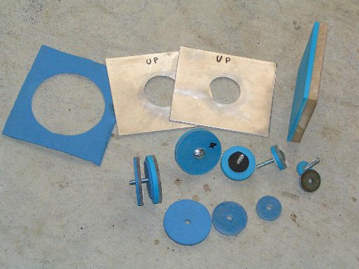
Shown in this photo are two calibration plates (one is all that’s really essential) and a foam seal (blue sheet with hole) for using these plates. The wooden plate with foam bonded to it is for sealing the cabinets test hole when performing leak testing. The smaller items are components of the ‘bungs’ to seal the orifice holes that are not being used for testing. Cabinet- The Cabinet is made from MDF wood (12mm thick) and was sized according to the sheet sizes available so that minimum cuts were required. It is basically divided into an upper and lower section; MDF was glued and screwed together for strength and air tight sealing. Please use the photos, schematic and read “what I’d do different” for a design guide. The dimensions shown in the schematic are for indication purposes only and it’s up to you to design and build the cabinet according to the thickness MDF etc you have available. Consideration must be given to strength so that vacuum doesn’t collapse the cabinet. The wood was spray painted for cosmetics and protection as MDF is easily damaged by water (yes, that colour is hideous. It’s all I had lying around!) The hole in the top for mounting test items is about 4” diameter as this is larger than most bore diameters of engines I test with, it has the lower edge chamfered for smoother air flow (I used a router, but could be filed by hand easily). What is hard to see in the photos is the 4 threaded inserts (captive ‘nuts’) around the hole to screw adapter fixtures down, these come from the hardware shop and insert into the wood under the top.
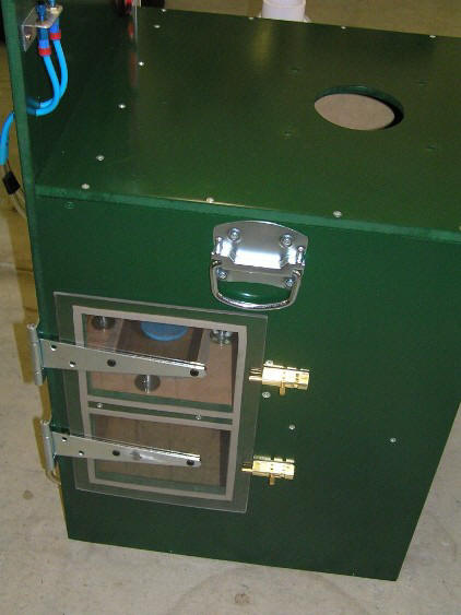
The side door allows access to the orifice plate for testing and the pressure sensing tubes during construction, It’s sealed by a foam weather strip. The sliding door ‘bolts’ and hinges are shimmed out and spaced so that when slid across and over the door they exert enough inwards force to seal firmly. A transparent Perspex door allows easy checking of what orifices are in use.
Handles mounted onto the sides and the accessory holder (aluminium tray, near side) are finishing touches.
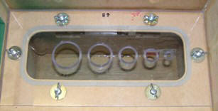
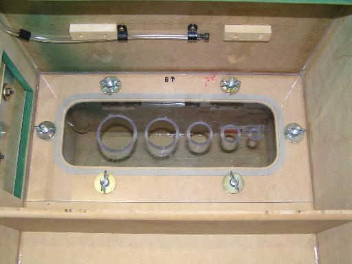
View with the lid removed. Visible is the orifice plate (no ‘bungs’ fitted in the photo) with captive bolts (bonded in) and wing nuts that allow the orifice plate to be turned over easily for blow testing of exhaust systems etc. Upper pressure sensing tube can be seen on the back wall, there is one below the orifice plate also, their ends are blocked and they have small holes along them (not visible). The wooden blocks on the back wall are what the laminar flow grid rests on.
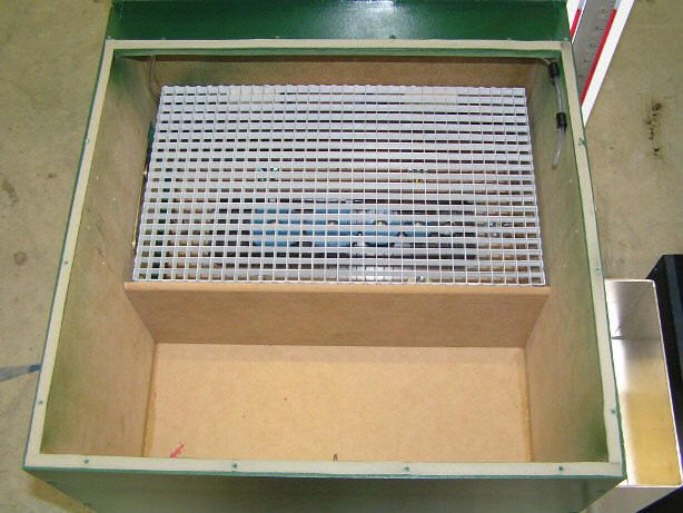
A view with the lid removed and the laminar flow grid in place above the orifice plate. The tube visible on the right is from the vertical manometer for measuring the test pressure.
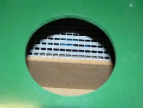
A view at an angle into the testing hole on the cabinet bench top when all assembled.
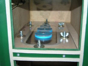
A picture of the bungs sitting in the orifice holes, viewed from the side door.
The approximate dimensions of the main cabinet (not including backboard) are 62cm high, 45cm x 45cm, the back board is 30cm high.
The airbox (not shown) is 48cm long, 33cm x 33cm, its bleed valves are 2.5”, ½” and ¾” diameter.
Calibration: The ideal result should be that a 100% reading would display on the inclined manometer if a test piece (or calibration plate) flowed the same as the selected measurement orifice. Calibrating with a plate that flows the same as the orifice is not really practical due to the difficulty of making holes with such precision so it is simply done with one that flows at least > %90 of the largest orifice hole (ie. Just made slightly smaller). If the calibration is done with the largest orifice selected then the smaller holes will be OK as this is the most critical one.
Using the bench: To use you need to have a small table kept handy with what each orifice flowed when tested. For example, for the above bench the following is used. Printed and laminated on paper and pinned (removed for photos) to the backboard near the inclined manometer for easy viewing. It shows the test results at 7” water for the orifice plate used in the photos; the fact that it was tested at 7” is irrelevant. Test Orifice- Flow CFM #1 143.2 #2 95.58 #3 48.02 #4 24.22 #5 5.31
Also sitting with the bench should be a copy of a table that allows any test pressure to be converted to another. Quite often you may be testing at a lower pressure; say 15” (perhaps your bench can’t reach higher pressures on large flowing items) and you wish to convert to 28” as this is the standard pressure often used by manufacturers and tuners. This table can be printed from the downloadable chart and laminated for longevity.
To do a test-
NOTE: before a test session the test hole should be completely sealed (wooden block with foam works well) and a flow test done to test for leakage, this should be recorded. If there is any leakage then this reading will need to be added to your test results, eg if 3 CFM of leakage is noted then a later test piece result of 125 CFM would need correcting to be 128 CFM. Things I’d do different:
Summary:
Accuracy of this unit has been tested at < % 0.5 compared to a Superflow SF-1020 at nearly all tested pressures and flow rates, upon saying that, knowing the actual flow of a test item is a goal but even a close CFM rate will usually be acceptable for normal work and calculations. The important thing is repeatability and resolution, you must be able to get consistent readings at a given pressure and orifice so that when comparing modifications even small improvements can be noted.
Any feedback will be very much appreciated and welcomed.
Good Luck!
All we ask is that if you find the information interesting then post a link on your site, It will encourage us to continue publishing! Thanks.
|
|
Send mail to DTecDevices@outlook.com with questions or comments about this web site. |