![]()
Lambda Testing Pre Vs Post Converter
|
|
|
|
Should I tune after the catalytic converter?
Purpose:
To show the practical effect of measuring fuel mixtures during tunning at the tailpipe compared to at the engine (pre-catalytic converter vs post-catalytic converter) with a ‘broad band’ oxygen sensor. This testing was done to determine the approach needed for successful tuning of performance vehicles.
Measuring of A/F ratio with ‘Broadband’ sensors, background information:
Sensors such as Bosch’s LSU family (and the required controllers/displays) are cheap, fast and incredibly accurate. They are used by Car manufacturers for both development calibration and in the actual production vehicles for fine closed loop control of air/fuel ratios.
Click here for information on DTec's Air Fuel Ratio Meter
It must be remembered that they are only measuring oxygen concentration to display the air fuel ratio in terms of Lambda (explained later). Combustion efficiency also has an effect on the available oxygen and therefore the final reading.
They do have sensitivity to hydrogen concentrations etc and also exhaust pressure, the effects are small enough to generally ignore (though most vehicle manufacturers ECU’s incorporate a pressure correction factor that can be implemented, specially in Turbo applications with higher back pressure).
Measuring of A/F ratio with 4 gas analyser, background information:
Common workshop style 4 gas analysers (measuring CO, CO2, HC and O2) generally use Non-Dispersive Infrared Spectroscopy (NDIR) principle for CO,CO2 and HC and a consumable chemical cell for O2 measurement.
The air/fuel information that they display is based on a complex calculation called the ‘Brettschnieder’ theorem after its creator. This formula basically looks at the composition of the exhaust by measuring the 4 gases and then calculates how much air and fuel must have been reacted to have that final result.
It is insensitive to combustion efficiency and catalytic converter operation (‘what goes in must come out’). The problem is with this equipment it’s expensive and the reaction time is too slow (often >5 seconds) for general performance tunning work and totally useless for transient testing.
Lambda vs air/fuel ratio, background information:
Lambda is a way of expressing air/fuel ratio that is independent of fuel composition. It is basically a ratio of how far away we are from that ideal air/fuel ratio for any particular fuel.
Every fuel has a chemically ideal (stoichiometric) mixture with air that allows complete combustion (theoretically) i.e. those who remember High school chemistry will understand about ‘balancing’ chemical equations. As all fuels have different compositions (Hydrogen & Carbon composition primarily) so therefore each will have a different amount of air required to combust it fully.
Lambda 1 is stoichiometric (ideal), 0.9 is 10% rich, 1.1 is 10% lean, regardless of fuel type.
Lambda 1 is neither best for economy or power, it is optimal for catalytic converter operation and therefore low emissions.
Examples of some fuels and their equivalent air/fuel ratios-
Lambda Petrol LPG Methanol Ethanol 0.90- 13.2 14.0 5.8 8.1 0.95- 14.0 14.7 6.1 8.6 1.00- 14.7 15.5 6.4 9.0 1.05- 15.4 16.3 6.7 9.5 1.10- 16.2 17.1 7.0 9.9
Lambda 1 with LPG would be 15.5:1 but will be 14.7:1 if running on petrol.
Displaying Lambda as an actual air/fuel ratio requires knowledge of the fuel composition. It is not safe to assume its 14.7 for petrol as even a small change or additives like ethanol in the fuel alters the stoichiometric point significantly (10% added makes it 14:1 not 14.7:1).
It is advised therefore to work in Lambda, not Air/fuel ratio.
Catalytic converter operation, background information:
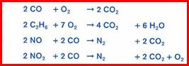
The modern ‘3 way’ catalytic converter takes care of Carbon monoxide CO, Hydrocarbons HC and oxides of Nitrogen NOx (NO and NO2). It does this using 2 main chemical reactions known as oxidization and reduction.
These conversions can only occur efficiently if we vary (cycle) the mixture a fraction of a percent either side of Lambda 1, as soon as this condition is not met the catalytic converter goes from being extremely efficient at conversion (>99%) to being practically useless for some of the conversion processes required.
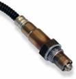
The effect of a converter working correctly in a production car can be seen by examining the operation of a pre and post converter sensor; these are conventional oxygen sensors, not broad-band. The rear sensor clearly does not follow the front sensor that’s cycling in time with the ECU altering the mixture. It almost reads a constant value and this shows correct operation of the system.
Oxygen sensor voltages. Production vehicle/sensors, Constant rpm and Lambda = 1 Blue= front ‘pre’ sensor, Red= rear ‘post’ sensor
The rear sensor can be made to alter it’s voltage by simply snapping the throttle open and therefore commanding a rich mixture. The catalyst does not work efficiently under the rich gas and therefore the rear sensor starts to read rich (high output), the same happens under deceleration when the injection is cut and the mixture goes lean (low output). Note the delays between the front and rear sensor readings; it is all to do with oxygen storage of the converter and the changing gas chemistry.
Oxygen sensor voltages. Production vehicle/sensors, Throttle repeatedly ‘snapped’ therefore varying Lambda. Note the delay from change in mixture (pre) until the converter outlet gases change (shown on post sensor) Blue= front ‘pre’ sensor, Red= rear ‘post’ sensor
Experiment to test the effect of a catalytic converter on the measurements taken with broad-band Lambda sensors:
A test engine was instrumented with Motec (PLM) broadband sensor equipment before and after the catalytic converter (boss’s welded into manifold and an additional tailpipe mounted probe as further reference). The engine was fitted with a programmable engine control system that itself used precision closed loop control of the mixtures based on broadband sensor feedback.
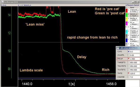
The mixture was adjusted progressively both ways from Lambda 1.4 (lean to point of miss fire) to 0.7 (rich) and the results recorded. Rapid ‘sweeps’ through the test mixture range were also performed to see how the catalytic converter affected the transient reading of the sensors.
A result of a rapid mixture change Lean to Rich, Note the delay between pre vs post sensors
Summary points:
Exhaust is best sampled before the converter if possible, this avoids delays, gains a slight increase in accuracy, faster sensor heating (closed loop), less moisture condensation exposure and less gas transport delays.
But, from this testing, the tail pipe measurements are shown to be acceptable for performance testing/tunning, especially since much of this work is done at Lambda’s that render the catalytic converter ineffective. Bear in mind though that rapid mixture changes may ‘dampen’ out the readings so when testing perform ‘ramp’ tests slowly and avoid sudden mixture changes.
Click here for information on DTec's Air Fuel Ratio Meter
All we ask is that if you find the information interesting then post a link on your site, It will encourage us to continue publishing! Thanks.
|
|
Send mail to DTecDevices@outlook.com with questions or comments about this web site. |