![]()
Ignition Coil Energy Testing
|
|
|
|
Ignition Coil Energy Testing, DIY Approach
What does it do?
Ignition coil stored energy is measured in milli Joules (mJ) and is relatively easy to measure with some simple DIY equipment. Coil energy encompasses time, current and voltage characteristics. Stored energy is a very important factor, it relates directly to spark intensity and burn time. Very few people seem to realise how simple it is to measure and what an important aspect of an optimum ignition system it is, electrical engineers dealing with automotive ignition systems certainly do!
This tester does not measure coil voltage output of the coil, it is for measuring stored energy which, as stated, is extremely valuable information.
The following equipment and procedure provides very repeatable results and is perfect for an “apples with apples” approach for comparing different inductive ignition coil designs in regards to their storage ability.
Principle:
Basically, coil energy is measured by ‘firing’ the test coils high voltage output into a zener diode to ‘clamp’ the voltage accurately at a known level. If we also measure spark current and duration (really just a discharge pulse but we’ll call it a ‘spark’) we have all the information we need to calculate the energy easily.
WARNING !!!!!!
This testing involves high voltages generated by ignition coils and therefore has the associated dangers (it can be lethal). Only build and operate this equipment if you are competent in this field.THIS INFORMATION IS PROVIDED IN GOOD FAITH. IN NO EVENT SHALL THE CREATORS OF THIS INFORMATION BE LIABLE FOR ANY DIRECT, SPECIAL, INCIDENTAL OR CONSEQUENTIAL DAMAGES OR CLAIMS BY THIRD PARTIES, DAMAGE TO EQUIPMENT, OR OTHER SIMILAR COSTS ARISING OUT OF ITS USE OR INABILITY TO APPLY IT.
Zener diodes are diodes that will conduct in the reverse direction when the voltage gets above their rating, sort of like a pressure relief valve. You can string them together to raise the voltage as it’s often hard to find individual high wattage ones with high zener voltage ratings. Using multiple diodes also helps them dissipate the heat better if only low wattage ones are available.
The zeners we used are automotive alternator diodes because we had them lying around (yes, they are zeners in most modern alternator rectifiers, a 12V alternator usually uses about 22V diodes). They are grossly overrated for this job. 5 Watt (W) zeners from the electronic store will work, but be careful when operating as you can only fire the coil into them for short periods or the heat build up will destroy them! This is not really an issue as you only need to fire the coil once to take a measurement. If you wanted to fire repeatedly into 5W zeners, rather than just a single discharge, then a couple of seconds of is all the test time before the solder melts!
75V 5W are commonly available but if you can cheaply source 20W or greater then that’s preferable. Higher voltage ratings are also good as it means you will need less diodes to reach 800V.
Simply join enough of the zeners up to achieve a rating of approximately 800V. Record the voltage for your later calculations. You could actually measure the total voltage under use but adding up the individual ratings will usually be fine eg 11 diodes used x 75V rating each = 825V.
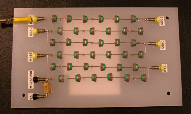
A conventional diode such as a common IN4007 (use any high spec diode) is also added to the zener ‘string’. In the photo this diode is barely visible in line with the coil input (yellow ‘banana jack’, top LH), just solder yours in series with the zeners as mounting in the banana jack was just for our development testing.
There is no need to have multiple high voltage input points as in the actual photo; these were only used for development work!
To measure the spark current a ‘shunt’ resistor is added in the circuit and the voltage across it measured with an oscilloscope. Choose a ‘neat’ value (100, 10, 1 or 0.1 Ω) to make the oscilloscope reading easy and use a low resistance as this will have a minimal effect on the circuit operation. Use a quality high wattage (5W or greater) resistor for durability. A 1Ω resistor would result in 1V measured for every 1A of current (100mV = 100mA) as Ohms law tells us that Voltage = Resistance x Current, so 1Ω isn’t a bad choice. Too small a resistor value and the voltages measured get hard to read accurately on the oscilloscope, spark current is generally less than 100mA! Resistor tolerance can be large so measurement/calibration is recommended.
The overall design is up to you, we mounted the diode string on an old plastic sheet, just make sure its an insulator material (wood is fine).
Procedure:
Coil primary current control is vital for good ignition systems as stored coil energy is related to coil current by a square rule (1/2 x primary winding inductance x primary current ²). It is important to ensure your testing is done with a well controlled primary current i.e. use the same ignition module or current regulated power supply to drive the coils for comparative testing.
Please read the tech article on the understanding and calibrating of ignition coil dwell time, for more information about coil characteristics and testing.
Fire the coil into the Zener string and measure the voltage across the shunt resistor on an oscilloscope. Determine the spark current and duration based on the shunt resistor value and use the following calculation.
Calculate energy with- ½ x duration x (spark current at start + spark current at end {which is basically 0}) x Zener voltage
If we use units of duration as milliseconds 'ms' and spark current as Amps 'A' then answer is directly in 'mJ'!
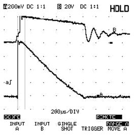
eg. 0.5 x 1ms x 0.08 A x 792v = 31.68 mJ (milli Joules)
The above example is based on the scope data below. Channel 2 (top trace) can be ignored; it is just coil primary voltage for reference to show how its duration matches spark current duration.
Lower trace is spark current, it was measured by passing the spark current through a measuring resistor to convert the current into an easy to read voltage. A 10Ω resistor (not an ideal choice but actually works fine) was used, therefore every 10 mV on the scope = 1mA of spark current. The zener ‘string’ used had a 792V rating.
Results:
The following are the energy test results from some common coils-
Test conditions:
Coil energy data is invaluable information for selecting ignition coils; however, coil voltage potential is another important characteristic that must be considered. It is very easy to have a good high energy system/coil that won’t generate enough voltage to fire plugs in a highly boosted engine. The charge times of the coil (dwell requirements) are also a vital consideration for high rpm operation. Detailed information on coil dwell and further testing can already be found in the “tech articles” page, and voltage potential testing will be discussed in an upcoming feature.
Enjoy!
All we ask is that if you find the information interesting then post a link on your site, It will encourage us to continue publishing! Thanks.
|
|
Send mail to DTecDevices@outlook.com with questions or comments about this web site. |